


Multiplexer
What is a multiplexer? How to use and implement it?

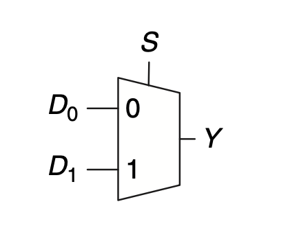
Multiplexers are among the most commonly used combinational circuits. They choose an output from among several possible inputs based on the value of a select signal. A multiplexer is sometimes affectionately called a mux.

The Mux logic equation can be built using a K-map:

And using this logic equation we can build the Mux using logic gates:

Or we can use tristate buffers also to implement a Mux:

Multiplexers can be used to implement basic logic gates like NOT, AND, OR, NAND, NOR, XOR, XNOR. This link shows each logic gate using 2:1 Mux in detail: https://vlsiuniverse.blogspot.com/2016/08/logic-functions-using-mux.html
2-input AND Gate:

Here the control lines are the inputs itself and the Y is simply what the Truth Table output should be:

We can see from the truth table that A and B simply shows us 4 combinations and those same combinations correspond to the 4 MUX selects, and we can see when A=B=1, the output Y=1 else all 0.
XOR Gate:

The XOR gate can be implemented by drawing the Truth Table and looking for a pattern:

We first separate the inputs A and B, and see that when A=0, output Y=B i.e output Y is simply what input B is. When A=1, the output Y=~B i.e output Y is invert of the input B.
AND Gate:

Writing the Truth Table for AND gate:

We first separate the input A, and see if A=0, output Y=0. Next is when A=1, output Y=B
4:1 Multiplexer
A 4:1 Multiplexer indicates there are 4 data lines D0, D1, D2, D3 and a 2 bit Select Line S, which selects one of those Data lines input to propagate to the output Y.

The 4:1 Mux can be implemented using three 2:1 Mux:

I have compiled a SystemVerilog Code with Test bench for a 2:1 Mux, 4:1 Mux on EDA playground https://www.edaplayground.com/x/PG4C
Source: Digital Design & Computer Architecture by Harris & Harris